4-Link Suspension Guide:
Anti-Squat, Anti-Dive, & Roll Center
One of the most common questions we get about suspension setup and tuning is how 4-link geometry affects the performance and handling of a vehicle. In this article we'll cover what we consider to be the three most important elements: anti-squat, anti-dive, and roll center.
The Basics of Anti-Squat, Anti-Dive, and Roll Center
When building a 4-link suspension, the lengths of the links, their positioning, and the angles at which they are mounted, will all determine how the suspension affects the vehicle chassis under acceleration, braking, and cornering. While a chassis with too much body roll can easily be improved with the addition of a properly tuned sway bar, undesirable rear squat and front nose dive characteristics can only be fixed be changing the 4-link geometry. To emphasize that point further, and because it is a very common mistake, a vehicle with too much rear squat under acceleration or too much nose dive under braking cannot and should not be fixed by using heavier springs and/or shock valving. These unwanted characteristics are caused by incorrect 4-link geometry and they can only be improved by changing that geometry.
Don't Over-Think It: There are many thick textbooks, expensive software, and hundred-page internet forums out there on the subject of 4-link geometry and it is very easy to get lost and frustrated. You are not building a Formula 1 racecar so don't expect to be plotting the movement of your suspension under every posible situation. The best advice we can give is to not over-think it, as long as you are familiar with the basic concepts of anti-squat, anti-dive, and roll center, and the axles move nice and smooth when you cylce the suspension, you will be in great shape.
Download a 4-LInk Calculator
The first step in either building a 4-link suspension or troubleshooting an existing suspension is to download one of these Triaged calculators created by Dan Barcroft and plug in the dimensions and weights it asks for. While they may look complicated, they are actually very easy to learn by just entering numbers and watching the outputs and graphics change.
Triaged 4 Link Suspension Calculator (.xls)
Triaged 3 Link Suspension Calculator (.xls)
Rear: Anti-Squat Explained
Anti-squat in a linked suspension system determines how the rear end of a vehicle moves under acceleration or upon the rear axle contacting an obstacle at speed. The anti-squat value is determined by the vertical angle of the rear links as they relate to the front axle position and the center of gravity of the vehicle.
How to Calculate Anti-Squat:
- Find the horizontal center of gravity height of the vehicle or use the crankshaft. (Yellow)
- Draw a line from the center of the front tire contact point up to the center of gravity line. (Dotted Green)
- Draw a line from that intersection to the center of the rear tires contact point. (Solid Green)
- Draw lines to extend the upper and lower rear links and find the point where they intersect. (Instant Center)
- The vertical distance from the ground to the instant center is the anti-squat value.
How Anti-Squat Affects the Vehicle:
- Anti-squat above 100% causes the rear end to move up and the suspension to unload under acceleration.
- Anti-squat under 100% causes the rear end to move down and the suspension to compress under acceleration.
- 100% anti-squat results in no movement under acceleration.
Rear: Anti-Squat Over 100%
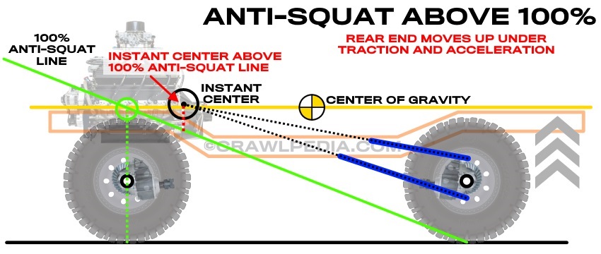
Suspension systems with anti-squat values over 100% will cause the rear end of the vehicle to raise up and unload the rear suspension under acceleration or when the rear tires contact an obstacle at speed. These characteristics are desired for drag racing and heavy acceleration applications because the forces that push the rear end up also push the rear tires down for more traction. At speed, however, when the rear tires impact an object, that immediate increase in traction will cause the power applied to the rear axle to raise the chassis up at the same time as the suspension is trying to compress and absorb the impact.
- Anti-squat between 140% and 180% works well for drag racing on smooth pavement with heavy rebound valving.
- Anti-squat between 110% and 150% works well for hardcore technical rock crawling and some styles of rock bouncing.
- Anti-squat between 100% and 130% works well for mud drag racing and some hill-n-hole racing.
Rear: Anti-Squat Under 100%
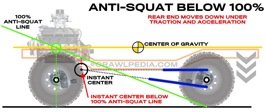
Suspension systems with anti-squat values under 100% will cause the rear end of the vehicle to drop down (squat) and compress the rear suspension under acceleration or when the rear tires contact an obstacle at speed. These characteristics are desired for desert racing to absorb rough terrain at speed because the impact forces are transferred directly to the rear suspension. Under hard acceleration, however, some of the power applied to the rear axle is used to compress the rear suspension which lifts up on the tires and robs traction and power.
- Anti-squat between 10% and 50% works well for high speed desert racing.
- Anti-squat between 20% and 80% works well for open road racing and rally racing.
- Anti-squat between 70% and 100% works well for rock crawling and trail running.
Rear: 100% Anti-Squat
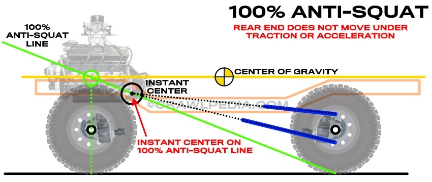
Suspension systems with 100% anti-squat values will have no effect on the chassis under acceleration or when the rear tires contact an obstacle at speed. These characteristics make the vehicle neutral and keep the power and suspension dynamics independent. While it's rare to have a vehicle permanently set up at 100% anti-squat, many people choose to make their suspension systems adjustable to above and below 100% anti-squat.
- 100% Anti-squat is a good universal default starting point for a multi-purpose vehicle.
- Anti-squat between 80% and 120% works well for almost every off-road application (excluding desert racing).
- Anti-squat between 80% and 120% works well for almost every street and track application (excluding drag racing).
Front: Anti-Dive Explained
Anti-dive geometry in a linked suspension system determines how the front end of a vehicle moves under braking and acceleration. The anti-dive value is determined by the vertical angle of the front links as they relate to the rear axle position and the center of gravity of the vehicle.
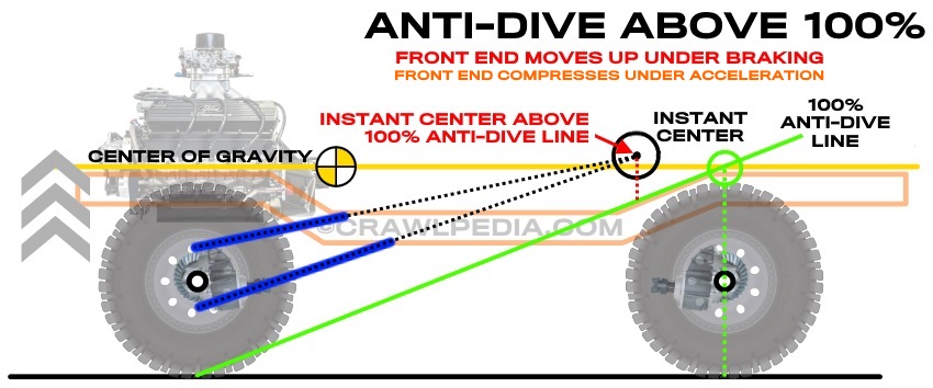
How to Calculate Anti-Dive:
- Find the horizontal center of gravity height of the vehicle or use the crankshaft. (Yellow)
- Draw a line from the center of the rear tire contact point up to the center of gravity line. (Dotted Green)
- Draw a line from that intersection to the center of the front tire's contact point. (Solid Green)
- Draw lines to extend the upper and lower front links and find the point where they intersect. (Instant Center)
- The vertical distance from the ground to the instant center is the anti-dive value.
How Anti-Dive Affects the Vehicle:
- Anti-dive above 100% will prevent the front end from compressing under hard braking and stiffens the chassis.
- Anti-dive above 100% will compressing the front suspension under hard acceleration in a 4x4 application.
- Anti-dive above 100% will significantly reduce rear weight transfer under hard acceleration.
- Anti-dive under 100% causes the suspension to compress under braking.
- Anti-dive under 100% causes the suspension to extend and lift under 4x4 acceleration.
- 100% anti-dive results in no movement and transfers all energy into the chassis.
Front: Anti-Dive Over 100%
Suspension systems with anti-dive values over 100% will cause the front end to stiffen up under hard braking to prevent the suspension from compressing which is ideal for aggressive braking and hard cornering. Under hard acceleration, high anti-dive geometry will cause the suspension to compress, thus keeping the front end down and under tension which is desired for steep hill climbs. As a trade-off, a suspension system with a high anti-dive setup with be less able to absorb rough terrain under hard braking as is required by rally cars and short course trucks.
- High anti-dive suspension geometry work well for aggressive street driving or pavement racing.
- High anti-dive suspension geometry is desired for hill-climb racing as it keeps the front end down under acceleration.
Front: Anti-Dive Under 100%
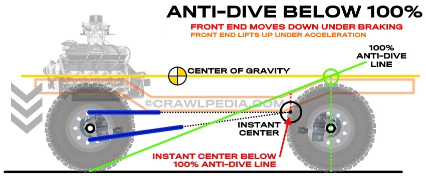
Suspension systems with anti-dive values under 100% will cause the front suspension to compress under breaking, often called nose-dive. Under acceleration, a low anti-dive geometry will cause the front end to lift and the suspension to extend which also shifts weight to the rear of the vehicle. These characteristics are great for aggressive driving on hard packed dirt tracks and hill climb racing. Many mud-drag racing vehicles use low anti-dive geometry to shift weight to the rear axle under acceleration and extend the front suspension to better absorb the terrain. Unfortunately, vehicle's with low anti-dive suspension geometry may experience excessive nose-dive under hard braking.
- Low anti-dive suspension geometry works well for rally racing or short course off-road racing.
- Low anti-dive suspension geometry is used by many rock bouncers to keep the suspension extended during a climb.
- Low anti-dive suspension geometry is desired in mud-drag racing to improve rear traction and absorbs rough terrain.
Front: 100% Anti-Dive
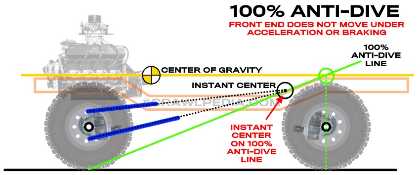
Suspension systems with 100% anti-dive values will have no effect on the chassis under braking or acceleration. These characteristics make the vehicle neutral and keep the power and suspension dynamics independent. For many applications, a 100% anti-dive front end may be a desirable starting point or default setting, especially if the 4-link mounts are fabricated to allow for adjustability above and below 100%.
- 100% Anti-dive is a great universal default starting point for many applications.
- Circle track racers often use low anti-dive on the left front and high anti-dive on the right front tire for improved left turns.
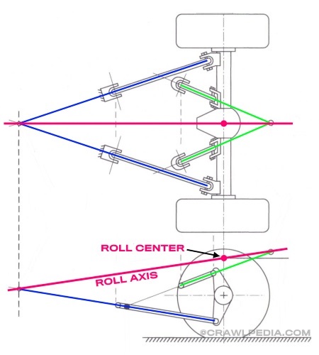
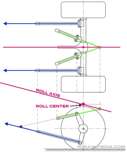
Roll Axis and Roll Center Explained
The roll axis and roll center of a vehicle's suspension system determin how much body roll or sway the vehicle will experience when cornering. The roll axis is the imaginary line drawn between the two points made where the lower links would eventually connect and where the upper links would eventually connect. In the case of a suspension with parallel links the roll axis line is simply going to be parallel with the parallel links. The point along the roll axis that is directly above the axle center line is the roll center.
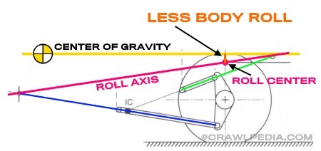
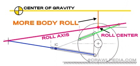
Body Roll Explained
The distance between the roll center and vehicle's center of gravity becomes the leverage factor for body roll. In other words, the further above the roll center the vehicle's center of gravity is, the more body roll the vehicle will experience during a turn. The closer the roll center is to the center of gravity, the less body roll the vehicle will experience and, in theory, if the roll center is on the center of gravity line, the vehicle would have no body roll.
One additional note about the roll center is that while the center of gravity of the vehicle always remains the same in relation to the chassis, the roll center and roll axis will move as the suspension cycles. For most applications this change in roll axis is not worth considering and the calculations should be done at ride height. For racing applications, however, watching the roll axis as the suspension compresses entering a hard turn may be worthwhile.
Finally, unlike anti-squat and anti-dive that can only be tuned by adjusting the 4-link geometry, a vehicle with too much body roll can easily be improved by installing a properly tuned sway bar without negatively impacting ride quality or suspension performance.
This 4-link guide is ©Copyright Crawlpedia.com - Please provide a link back to this page when copying.
Data is accurate to the best of our knowledge and is offered as-is with no guarantee.

More Shock Guides:
Shock Rebuild Instructions - Detailed step-by-step instructions for rebuilding high-performance shocks.
Shock Rebuilding Tools - A list of tools needed to service high-performance shocks and coilovers.
Shock Valving Guide - A guide to high-performance shock valving and valving shim configurations.
Shock Tuning Guide - A guide to how high-performance shocks are tuned and valved to work well.
Shock Valving Shim Stack Examples - A list of common, basic valving shim stack configurations for high-performance shocks.
Coilover Spring Rate Calculator - A calculator to help you determine a good starting point for coilover spring rates.
Shock Rebuild Parts - A link to Filthy Motorsports' shock parts page.
How To Measure For Coilovers - Order the right size shocks and coilovers by following these detailed instructions.
Coilover Install and Setup Guide - Proper coilover installation, setup, and fine tuning instructions.
Coilover Spring Re-Calculation Guide - How to easily correct coilover spring rates to achieve your desired ride height.
ORI STX Struts Guide - An introduction to ORI STX Struts, how they work and how to tune them.
Hydraulic Bump Stop Guide - A detailed overview of hydraulic bump stops and jounce shocks for off-road use.
Filthy Motorsports
High performance off-road racing parts and professional shock tuning. Learn more at
FilthyMotorsports.com
Shock Service, LLC
Professional shock tuning and rebuilding services for King and ADS shocks. Learn more at
ShockService.com
Polar Cryogenics
Cryogenic treatment improves strength and longevity of gears, axle, and brakes. Learn more at
PolarCryogenics.com
Crown Race Gears
Race-spec ring and pinion gears for desert racing, rock bouncing, and rock crawling. Learn more at
RaceGears.com