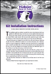
Ring and Pinion Gear Tooth Pattern
Automotive ring and pinion gears must be installed and set up in a very specific way to ensure that they will run smoothly and reliably. This is done using gear marking compound and checking the gear tooth pattern.
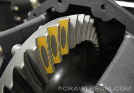
While there are many viable gear tooth patterns, as will be explained in this guide, the one shown in the image above is the most desirable (although, not always achievable).

Ring and Pinion Gear Installation Basics
Installing new ring and pinion gears or re-installing existing gears with new bearings and seals is a relatively simple process, however, it can get frustrating if you are not prepared. There is always a bit of fear or hesitation associated with attempting something you have never done before, but know this is something that any mechanically inclined person can do themselves by following these instructions.
As always, before starting any installation, lay out all of your parts, review the part numbers and descriptions, and compare them to the items being replaced to ensure everything is correct.
If this is your first time installing ring and pinion gears, the best advice we can give you is to get yourself into the right mindset prior to starting this project. Plan ahead and allow for plenty of time to do the install because chances are you will need to assemble and disassemble your differential a few times to get the gear tooth pattern just right.
Finally, don't bolt up the differential cover until you are completely satisfied with the result. If possible, once finished, let the axle or differential sit overnight and come back fresh the next day to review the installation. Remember, if it takes an extra hour to adjust it one more time to get it just right, this is something you won't have to do again for a very long time and you will have the confidence of having completed the task correctly.
Ring and Pinion Gear Terminology
To understand how ring and pinion gears need to be set up, it is important know the basic terminology of gears. The following images highlight the areas of the ring and pinion gear set that you need to be familiar with:
| Ring Gear |
The large round gear that bolts to the differential. Also sometimes called the crown gear. |
| Pinion Gear |
The smaller, long gear that is driven by the driveshaft to turn the ring gear. |
| Tooth Face |
The sides of the gear teeth that contact the other gear. Both forward and reverse. |
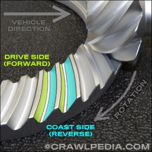
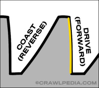
| Drive Side |
The side of the tooth, either on the ring gear or pinon, that is engaged when driven forward. |
| Coast Side |
The side of the tooth, either on the ring gear or pinon, that is engaged when driven backwards. |
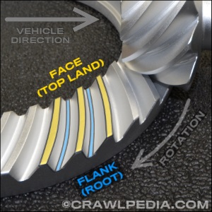
| Gear Face |
The surface at the highest point of the gear tooth, facing the other gear. Also referred to as "top land". |
| Gear Flank |
The deepest point of the valley between gear teeth. Also commonly called the gear "root". |
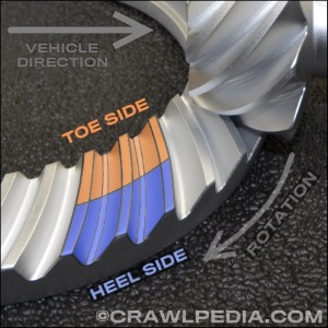
| Toe Side |
The side of the gear tooth face closest to the center of the ring gear. (Small side of the pinion gear.) |
| Heel Side |
The side of the gear tooth face closest to the outside of the ring gear. (Large side of the pinion gear.) |
This ring and pinion installation guide is ©Copyright Crawlpedia.com - Do not reproduce without written permission from Crawlpedia.
Always wear gloves and safety glasses and follow all tool, equipment, and part instructions when installing ring and pinion gears.
Drive and Coast Tooth Sides
Ring and pinion gear teeth are cut with the drive faces positioned closer to vertical and the coast faces at a steeper angle. The drive faces are also typically convex, curving outward while coast sides are concave, curving inward. Other than some very uncommon applications, your primary focus when setting up gears is going to be on the drive face of the gear teeth as this is the side that will be pushing the vehicle forward.
Ring and Pinion Gear Setup Tools
To set up automotive ring and pinion gears, you will need a few specialty tools. Primarily, you will need some Gear Marking Compound to check your gear tooth pattern and a 0-1" Dial Indicator with a Magnetic Base to check you backlash. If you don't have a large hydraulic press with the proper tooling to removing bearings, we recommend purchasing a Carrier and Pinion Bearing Puller tool. For larger axles, it is also very helpful to have a Differential Housing Spreader Tool which makes adding carrier bearing shims significantly easier.
While there are other ways to hold your pinion yoke from turning when tightening the pinion nut, this Pinion Yoke Wrench Tool is cheap and universal. Finally, if you will be setting up many different ring and pinion gears, it is worth investing into a high quality Pinion Depth Setting Tool Kit.
As an Amazon Associate, we earn a small commission on purchases which does not affect your pricing.
Ring and Pinion Gear Tooth Patterns
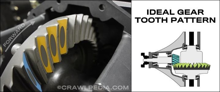
After installing your ring and pinion gears for the first time by following the installation instructions that came with your gears, you are ready to do your first gear tooth pattern check. This is done by applying gear marking compound to 3 or 4 teeth on the ring gear and then rotating the pinion past those gears several times while also applying an opposing force to the ring gear by hand. The pinion gear will wipe off the marking compound where the two gears make contact, thus showing you the gear tooth contact pattern. Compare your pattern to the examples below and make any necessary adjustments. Repeat this process until your pattern matches an ideal gear tooth pattern.
|
The ideal gear tooth pattern will have the contact patch on both the drive and coast sides of the teeth centered between the face and the flank as well as the toe and the heal. If your gear tooth pattern looks like the photo above, you have a perfect gear tooth pattern.
|
|
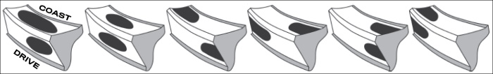
IMPORTANT - Not all gears are machined with a centered contact patch.
While the above centered contact patch is the ideal, the primary focus is centering the contact patch vertically between the flank and the face. When the contact patch is centered vertically, your pinion depth is correct. The following image shows additional acceptable gear tooth patterns. Note how all of the contact patches are centered vertically on the teeth.
|
|
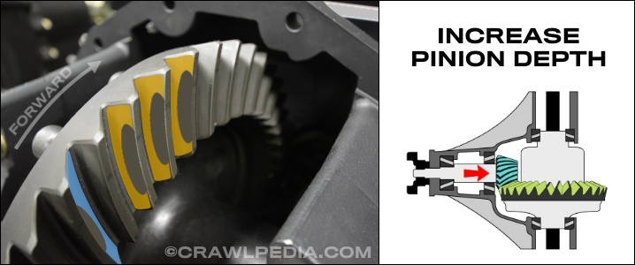
If your gear tooth pattern is too high, up towards the gear face, you will need to increase your pinion depth by using more or thicker pinion shims. This will move the drive side contact point down towards the gear flank (root) and slightly in towards the toe. The coast side contact pattern will also move down towards the flank but out slightly towards the heel of the ring gear.
|
|
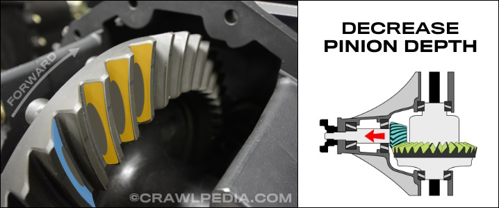
If your gear tooth pattern is too low, down towards the gear flank (root), you will need to decrease your pinion depth by using fewer or thinner pinion shims. This will move the drive side contact point up towards the gear face (top land) and slightly out towards the heel. The coast side contact pattern will also move up towards the face but in slightly towards the toe of the ring gear.
|
Ring and Pinion Gear Backlash
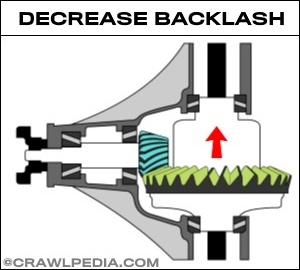
Backlash is the gap between the ring gear and the pinion gear. The size of the gap is specific to each axle, and the specifications are different between new and used ring and pinion gears. To find the proper backlash specifications for your application, please see our Ring and Pinion Set Up Specifications Guide
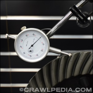
Measuring backlash is done using a dial indicator with a magnetic base that you attach to the axle housing. With the needle positioned as straight as possible on the drive face of one of the ring gear teeth (the heel side), move the ring gear back and forth while holding the pinion yoke so it doesn't rotate. The distance that the ring gear moves is the backlash.
Backlash is adjusted by moving the ring gear closer to the pinion for less backlash or away from the pinion gear for more backlash. For most axles, this is done by moving carrier bearing shims from one side of the carrier to the other. Some axles, like Ford 9 Inch and some Toyota axles, this is done with their built-in screw adjusters.

Final Inspection and Gear Break-In
Once you are happy with your installation and gear tooth pattern, perform a final inspection and double check that your pinion bearing preload is correct and that your backspacing is within the recommended range. Do a visual check to make sure that the differential housing is clean and then bolt on the differential cover and add the recommended gear lube. Finally, always make sure to follow proper gear break-in procedures.
This gear tooth pattern guide is ©Copyright Crawlpedia.com - Please provide a link back to this page when copying.
Data is accurate to the best of our knowledge and is offered as-is with no guarantee.
More Gear and Axle Guides:
Differential Locker Comparison - A detailed comparison of popular differentials and lockers.
Ring and Pinion Setup Specs - Ring and pinion gear setup specifications for popular axles.
Gear Ratio Finder - Find the ideal axle gear ratio for your new larger or smaller tires.
Gear Ratio Calculator - Calculate the gear ratio of gears based on their tooth count.
Ring and Pinion Ratio Variations - An explanation of why some ring and pinion gear ratios vary.
Thick Gears and Carrier Breaks - Thick ring and pinion gears and differential carrier breaks explained.
Filthy Motorsports
High performance off-road racing parts and professional shock tuning. Learn more at
FilthyMotorsports.com
Shock Service, LLC
Professional shock tuning and rebuilding services for King and ADS shocks. Learn more at
ShockService.com
Polar Cryogenics
Cryogenic treatment improves strength and longevity of gears, axle, and brakes. Learn more at
PolarCryogenics.com
Crown Race Gears
Race-spec ring and pinion gears for desert racing, rock bouncing, and rock crawling. Learn more at
RaceGears.com